
A Programmable Logic Controller (PLC) is a specialized computer with various inputs and outputs used to control and monitor industrial equipment based on custom programming. Its primary function is to manage the motions of automated handling equipment in a facility, such as conveyors and stacker cranes. The PLC then turns on and off relays, motors, and signal beacons on every machine.
PLCs have real-time operation as their defining quality. That is to say, in a few milliseconds they can react and turn the machinery’s movements active.
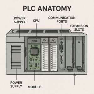
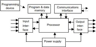
PLCs consist of various parts. One is the CPU, which stores all pertinent data and runs the PLC program. Modules in PLCs also facilitate the relocation of the physical connection between automated systems and the industrial computer. Likewise, PLCs require hardware and software to interpret the instructions and functions every machine requires to follow and execute.
The PLC analyzes the data and generates commands for the handling equipment using the information the sensors and input devices linked to every machine acquire. Imagine, for instance, a conveyor running a pallet straight to a lift on its own. The PLC will order the pallet to be delivered to the lift and subsequently moved to the matching level when the sensor detects the unit load.
Digitizing and automating all movements allows the PLC to also track and document real-time data, including operating temperature or machine performance.
How Does a PLC Work?
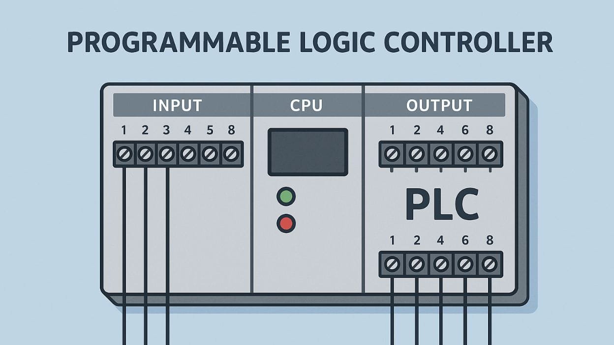
PLCs are basically small computers used in industries, and they have parts that can be added or changed to help automate different control tasks. Nearly all modern industrial automation relies on PLCs. A PLC has a lot of parts, but you can mostly group them into these three categories:
- Processor (CPU)
- Inputs
- Outputs
Results
PLCs gather information from the factory floor by keeping an eye on the signals from all the machines or devices that are linked up. The program logic checks these inputs, which then alters the outputs to any connected devices. You can connect the same machine to both the inputs and outputs on a PLC. For example, you might have a valve position sensor linked to the inputs while controlling that valve’s position through the outputs. A program can check where the valve is right now, see if it needs to change, and then adjust the valve’s position accordingly.
PLCs usually differentiate between digital (or discrete) and analog I/O. Digital I/O works just like a regular light switch, where it can only be in one of two positions: on or off, with nothing in between. Analog I/O works similar to a dimmer switch, allowing the state to be set anywhere from fully on to completely off.
It’s simple to see that there are two main types of input data for PLCs: device input data, which comes from machines or sensors automatically, and user input data, which is created by a human operator through an HMI or SCADA system.
The data from the devices comes from sensors and machines that provide information to the PLC. This might involve:
- On and off states for stuff like mechanical switches and buttons.
- Analog readings for stuff like speed, pressure, and temperature
- States of things, such as pumps and valves being opened or closed
- Inputs that people help with can be things like pressing buttons, using switches, or sensors from devices such as keyboards, touch screens, remotes, or card readers.
Components of PLC
What Are the Main Types of PLCs?
There are a lot of different types of PLCs, but they mostly fit into one of three main groups:
- Fixed CPUs are built into small PLCs, providing affordable options for basic tasks.
- Modular CPUs are used in bigger PLCs, which lets you customize and expand the system.
- Soft CPUs are software-based processors that operate on industrial PCs. They provide a lot of flexibility and can easily connect with IT systems.
How does PLC programming work? Languages and Methodologies
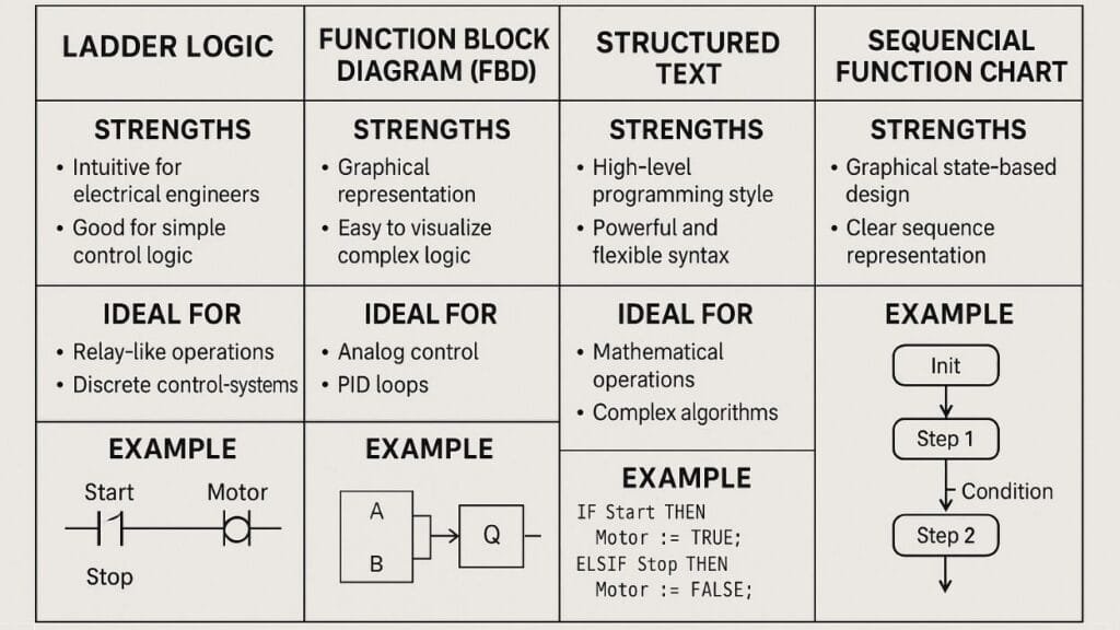
1. Ladder logic is the old way of talking in a PLC.
Ladder Logic is the computer language that Programmable Logic Controllers (PLCs) use the most. Its name comes from the fact that it looks like a ladder, with two straight rails and horizontal rungs in between them. This graphical language was made to look like relay logic diagrams so engineers and electricians who are used to working with physical control systems can easily understand it.
In Ladder Logic, programs run from left to right and from top to bottom. Usually, the right rail is the ground, and the left rail is the flow of power. Contacts (inputs), coils (outputs), and function blocks are some of the different parts that make up rungs.
Pros of using Ladder Logic:
- Visualization of control reasoning that is easy to understand
- The instructions are simple enough for electricians to understand and fix.
- Visualization of program running in real time
- A lot of backing and acceptance in the industry
- It can handle both easy and difficult control jobs.
What Ladder Logic Can’t Do:
- Large programs can get complicated and hard to run.
- Not much help for organized programming ideas
- Not the best for doing complicated math or changing data.
- Could need more memory and time to run than text-based languages
Some common ladder logic steps are:
- Always Open (NO) Contact: This is an input condition that needs to be true (on) for power to move.
- Open Most of the Time (NC) Contact: This is an input condition that needs to be false (off) for power to move.
- Output Coil: This is an output that gets powered up when electricity runs through it.
- Timer: Used for controlling things based on time
- Counter: Something that keeps track of events or operations
- Compare: Used to see how two numbers compare.
- Math: Used for simple math tasks
Ladder logic is still often used to program PLCs because it is easy to use and has a direct connection to hardwired switch logic. But as control systems get more complicated, it is often used with other PLC computer languages to make the most of what each one does well.
2. Function Block Diagram (FBD): Programming a PLC Visually
This is a graphical programming language for PLCs called Function Block Diagram (FBD). It shows how a system works by showing how different function blocks are linked. This method is based on the idea that data flows between processing elements, which makes it perfect for complicated algorithms and process control.
In FBD, programs are made by linking function blocks together with lines that show how data or signals move. Each function block does a certain task, like a math calculation, a logic process, or a control function. By connecting these blocks’ inputs and outputs, you can make the control logic you want.
FBD is different from ladder logic in a number of important ways:
- For example, ladder logic looks like a relay circuit, and FBD looks like an electrical circuit diagram or a flowchart.
- Data flow orientation: FBD makes it easy to understand how data goes through a system by showing it clearly.
- Reusability: It’s easy to mix and use function blocks again, which supports modular programming.
- Operations in math: FBD works better for complicated math and computer operations.
- Abstractions: FBD lets you use more abstract levels, which makes it easier to show complicated systems.
These are some common function blocks found in PLCs:
- AND, OR, NOT, and XOR gates
- Latch and flip-flops
- Counts and timers
- Controllers for PID
- Functions in math (like add, subtract, multiply, and split)
- Blocks for comparison
- Blocks for changing data
- Blocks for communication
For applications that need complex algorithms, continuous processes, or activities that use a lot of data, FBD is especially helpful. It makes control logic and data flow easier to understand visually, which makes it easier to build and fix complex control systems. FBD and traditional ladder logic programming have become more popular in PLC applications as industry processes get more complicated.
3. Structured Text (ST): Programming a PLC with text
Structured Text (ST) is a high-level, text-based language for writing PLCs that takes ideas from Pascal, BASIC, and C. It’s a powerful and adaptable way to program PLCs that works especially well for complicated algorithms and data manipulation jobs.
Some important things about structured text programs are:
- Text-based syntax: Like traditional computer languages, programs are written as a list of statements.
- Structured programming: ST allows IF-THEN-ELSE conditionals, CASE statements, and different loop structures, such as FOR, WHILE, and REPEAT.
- Strong data typing: Variables must be defined with the right data type. This makes the code more reliable and easier to read.
- Support for complicated math operations: ST can easily handle complex calculations and routines.
- Support for arrays and structures: This makes it easy to work with big sets of data and complex data structures.
- User-defined functions and function blocks: This makes code modular and useful.
For complicated algorithms, ST has a number of benefits:
- A short way to show complicated logic: ST is better than graphical languages at expressing complicated methods in a smaller space.
- Syntax that software workers are used to: It will be easier for coders who already know how to use traditional languages to switch.
- Effective execution: ST code processing is often more effective than graphical languages.
- Better for jobs that involve math and processing data: Formulas and data changes can be shown naturally.
- Making it easier to set up complicated control systems: Conditionals and loops that are inside of loops are easier to use in ST.
Here is a piece of code that shows how to use ST grammar for a simple temperature control system:
VAR
Setting point: REAL = 25.0; Temperature: REAL; HeaterOutput: BOOL; END_VAR
IF Temperature < (1.0 sets) IF Temperature > (Setpoint + 1.0) THEN HeaterOutput = TRUE; ELSE IF (HeaterOutput is not true) THEN END_IF;
With a 1-degree delay, this code checks to see if the temperature is below or above the setpoint and then turns on or off the heater based on that.
When comparing ST to other computer languages:
- Grammar: Some parts of ST’s grammar are like those in Pascal, and some are like those in C. Pascal coders will know what these keywords mean: VAR, BEGIN, END, IF, THEN, and ELSE.
- Types of data: ST supports commonly used data types in C and Pascal, like BOOL, INT, and REAL. It also allows PLC-only types, like TIME and DATE.
- Scope: Unlike C or Pascal, ST is made to be used for writing PLCs, with a focus on real-time control tasks and cyclic execution.
- I/O handling: ST lets you directly access the inputs and outputs of a PLC, which isn’t possible with most other languages.
- Execution model: Unlike most software programs, which run one after the other, ST programs run in a loop that never ends.
- Functions that are standard: ST has built-in functions for PLC-specific jobs, like timers and counters, that you won’t find in general-purpose languages.
Even though ST is a lot like other computer languages, it is designed to work best in a PLC setting. It combines the power of text-based programming with features that are only useful in industrial control applications. This makes it a great choice for PLC systems that need to do complicated mathematical calculations, process large amounts of data, or control complex algorithms.
Sequential Function Charts (SFC): Programming a PLC Based on a Process
Sequential Function Charts (SFC) is a graphical programming language made just for programming PLCs to handle processes in a certain order or in parallel. SFCs are useful for applications with clear operational states or steps because they give a high-level, visual representation of the control process.
There are three main parts that make up the structure of an SFC:
- Steps: Show different stages or states of the process.
- Transitions: Write down the steps you need to take to move from one to the next.
- Actions: List the tasks that need to be done in each step.
- Steps are shown by changes between rectangles and horizontal lines. Actions are usually linked to steps and written in their own blocks.
SFCs manage linear processes by carrying out steps in a set order. Transitions decide when to move from one step to the next. The process starts with the first step and moves on to the next steps based on the factors for each transition. Using more than one branch can show multiple processes running at the same time or different phases.
Here is an example of a basic SFC program that helps fill and empty a tank:
[Initial Step] | (Start Button Pressed) V [Fill Tank] | (Tank Full OR Max Time Reached) V
[Mix Contents] | (Mix Time Elapsed) V [Empty Tank] | (Tank Empty) V
[Finish Step]
This is an example:
- When you press the Start button, the process begins.
- It fills the tank until it’s full or until a certain time is up.
- For a certain amount of time, the contents are mixed.
- The tank is now empty.
- The process is over, but it can be started over from the first step.
When used in certain situations, SFCs can be helpful in the following ways:
- Clear visualization of process flow: SFCs make sequential processes easier to understand and fix problems with by showing them in a way that makes sense.
- Manage complex sequences more easily: Compared to other PLC languages, SFCs offer a more organized and manageable way to program processes with multiple states or activities running at the same time.
- Better safety and error handling: SFCs make it easy to define safe states and mistake recovery methods, which is very important in many industrial settings.
- Better documentation: Because SFCs are graphical, they have their own documentation, which makes it easier for everyone on the team to understand and keep up with the control system.
- Flexibility in implementation: SFCs can be used with different PLC computer languages, so developers can pick the language that works best for each part of the control system.
- Alignment with industry standards: SFCs are part of the IEC 61131-3 standard, which makes sure that different PLC systems can work with each other and encourages standard ways of programming.
- Batch processes efficiently: SFCs are perfect for putting in place recipe-based control systems in industries like food production or chemical processing where batch processes are widespread.
SFCs work really well in situations with different operating states, complicated sequences, or processes running at the same time. They are especially useful in fields like making medicines, cleaning wastewater, and automatic assembly lines, where it’s important to see the whole process clearly and follow set steps exactly for safety and quality reasons.
A PLC’s Role in SCADA & HMI Systems
SCADA and HMI systems enable users to view data from the manufacturing floor and provide user interfaces for control and monitoring — and PLCs are an essential hardware component element in these systems.
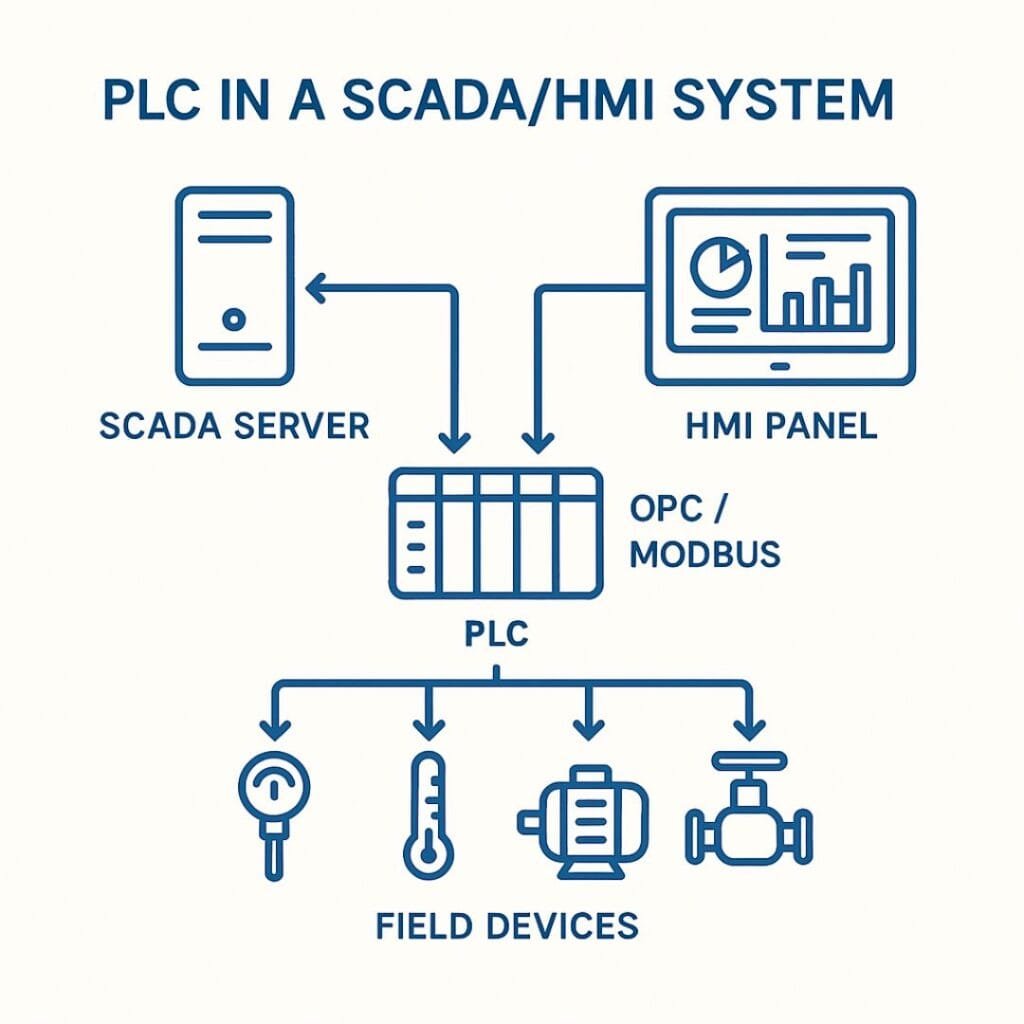
PLCs act as the physical interfaces between devices on the plant or manufacturing floor and a SCADA or HMI system. PLCs can communicate, monitor, and control complex automated processes such as conveyors, temperature control, robot cells, and many other industrial machines.
Discrete and Analog I/O
Inputs and outputs are often abbreviated with the term “I/O.” In the dishwasher example above, we treated every input and output as a discrete or digital signal.
Discrete signals are signals that can only be on or off. These are the simplest and most common types of I/O. In our example, we did not use any analog I/O.
Although there may be some use of analog I/O within a dishwasher control system, I wanted to keep this example simple.
With analog signals, instead of only on/off or open/closed possibilities, you may have 0 – 100%, 4 – 20 mA, 0 – 100 degrees Celsius, or whatever it is you are measuring as an input or driving as an output. We will cover this in more detail in part 3 of the Beginner’s Free PLC Training series.
What Will Happen to PLCs in the Future?
The industry is still getting new products, including things like Programmable Automation Controllers (PACs). These devices mix the features of PLCs with more advanced PC capabilities, and there’s also industrial embedded hardware coming out.
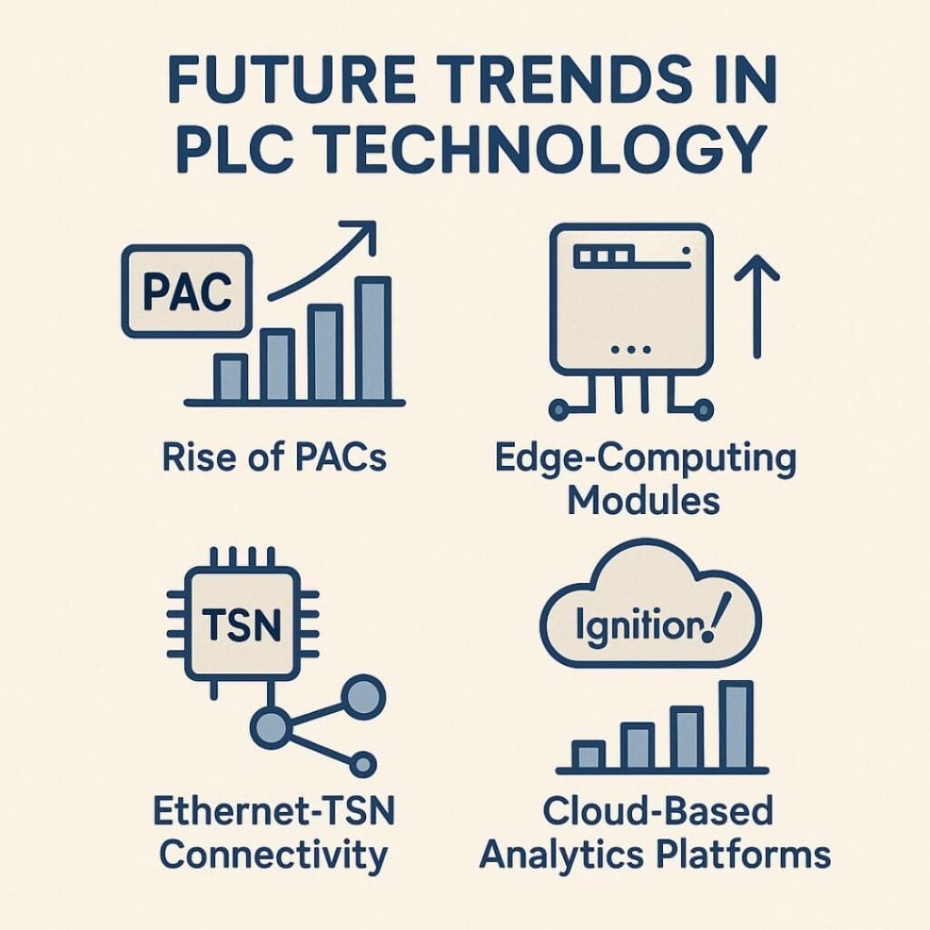
Even with these new products, PLCs are still popular because they are easy to use, not too expensive, and really helpful. Software like Ignition will help organizations get the most out of their resources for a long time.